| ✕ | ||
| ◁ | ▷ | |
| Hallo Test |

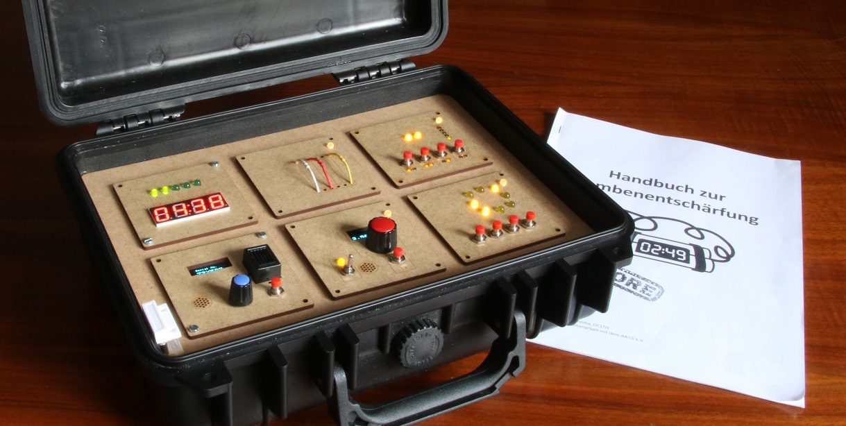
Inspired by the game Keep Talking and Nobody Explodes, I developed a hardware version of a bomb to be defused.
I had only heard of the game "Keep Talking and Nobody Explodes" when we were looking for potential games or puzzles for a "radio scavenger hunt" in our youth group at the local ham radio club. That’s when I remembered this communication-based video game, where players work together – one on the computer, the others with the manual – to defuse a bomb. We tried the game with a few people (VR makes it even more fun!), and I immediately knew: This game was just begging to be built using some microcontrollers. Not long after I had the first prototypes set up on a breadboard and developed the first PCB not much later.
One or two players are in front of the bomb – they are the defusers. The rest have the manual – they are the experts. The crucial rule is that neither side can see the other’s information! That means defusers can’t look at the manual, and experts can’t see the bomb.
As soon as the bomb’s timer starts, the two teams have limited time to solve the various puzzles and defuse the bomb. It requires teamwork, as the defusers rely on the information from the experts.
The bomb is modular. The timer is always present – it's the control center and also displays the remaining time. Then there are modules with different puzzles, which can be combined freely. Each module is designed so that defusers can only solve it with the help of the experts. If all modules are solved, the bomb is defused. If time runs out or too many mistakes are made, the bomb explodes.
Some modules involve simple logic puzzles, while others are based on technical knowledge (everything required to know is explained in the manual). For example, there's a module where binary numbers must be interpreted or one where a resistor has to be correctly identified by its color bands. So you casually learn bits of specialized knowledge from amateur radio, electrical engineering, or digital technology.
The manual comes in two variants: “Easy” and “Hardcore”. The easy version is especially suitable for beginners or those who just want to try the game. The instructions are short and easy to follow. The hardcore version is for more ambitious players who want an additional challenge. The puzzles are more complex and require a bit of practice. The bomb must be set accordingly to match the difficulty level (see “Appendix – Game Master Controls” in the manual).
For a standard game, a simple visual barrier between the two groups is enough. To increase the difficulty, defusers and experts can be placed in separate rooms and communicate via (PMR) radios. This restricted simplex communication makes the game significantly harder and can be a fun addition to the game.
If you own all the modules, you can play the campaign found in the “Appendix – Campaign” section of the manual. These are suggestions for different combinations of modules with a progressive difficulty.
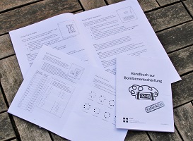
The manual for the experts contains all the information needed to defuse the bomb. It consists of several parts: besides general information about the bomb, it also includes appendices and, most importantly, instructions for each module.
Manual (Easy)
Manual (Hardcore)
The bomb is available as an electronics diy kit from AATiS e.V. (The page is German only).
The build instructions can be found starting March 2020 in Praxisheft 30 from AATiS (German only).
These images show one of the modules as a kit:
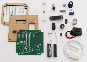
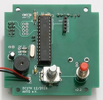
The control center of the bomb consists of two PCBs, responsible for displaying the time, querying the modules, and managing settings.
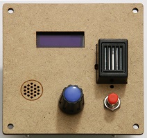
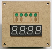
The main part of the bomb consists of various puzzle modules, each of which must be individually defused to prevent the bomb from "exploding" as a whole.
The following modules have been implemented:
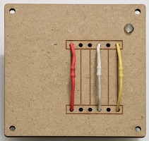
You have to determine which wire has to be removed, based on the combination of wires and some external factors.
Difficulty: ★☆☆☆
01 Wires at AATiS
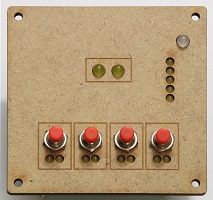
Binary numbers (from 0 to 3) have to be correctly interpreted and the result also memorized...
Difficulty: ★★☆☆
02 Binary Numbers at AATiS
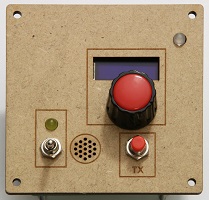
A Morse code has to be deciphered and the correct frequency has to be set.
Difficulty: ★★★☆
03 Morse at AATiS
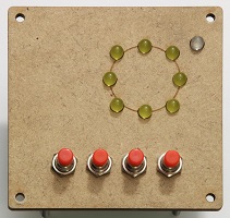
A module where a pattern of LEDs indicates which buttons have to be pressed.
Difficulty: ★☆☆☆
04 LED Circle at AATiS
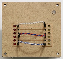
Similar to the "Wires" module, you have to determine which wire to remove and which to leave in place.
Difficulty: ★★★★
05 Twisted Wires at AATiS
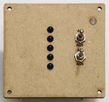
A handful of inputs, logic gates, and two outputs that have to be configured correctly.
Difficulty: ★★★☆
06 Logic Gates at AATiS
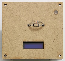
The correct resistor has to be inserted. Which one to insert is determined by the resistor color code.
Difficulty: ★★☆☆
07 Resistor at AATiS
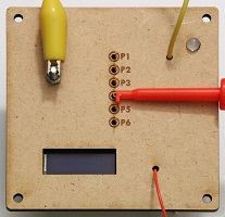
Following a flowchart, you have to measure at the test points and create the correct wire bridges.
Difficulty: ★★★☆
08 Volt Meter at AATiS
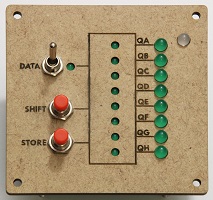
Like a real shift register, you have to manipulate the inputs to configure a specific sequence in the register.
Difficulty: ★★★★
09 Shift Register at AATiS
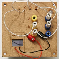
There's a hidden circuit behind the points A to F. You need to figure out the schematic to connect the plugs correctly.
Difficulty: ★★★☆
10 Schematic at AATiS
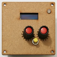
The displayed characters have to be entered as hexadecimal ASCII codes.
Difficulty: ★★☆☆
11 ASCII at AATiS
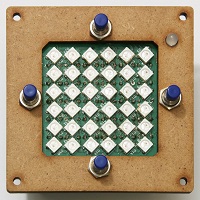
The marker has to be navigated through an invisible maze.
Difficulty: ★★★☆
12 Maze at AATiS
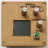
Depending on the wave form shown, the oscilloscope has to be configured accordingly.
Difficulty: ★★★★
13 Oscilloscope at AATiS
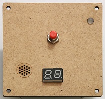
Whenever this module activates, you have to press the button at the correct moment.
Difficulty: ★☆☆☆
50 Nervous Button at AATiS
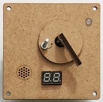
You have to ensure that the two rotating parts never touch each other.
Difficulty: ★★☆☆
Will not be available.
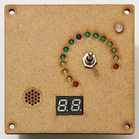
You have to make sure that the wandering LED never touches the red areas by toggling the switch every now and then.
Difficulty: ★★☆☆
52 Tone Generator at AATiS
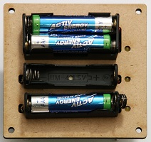
Adds a few batteries as a visual feature, but the module has no effect on gameplay.
Will not be available.
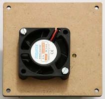
Adds a fan as a visual feature, but the module has no effect on gameplay.
Will not be available.
Currently, no new modules are under development. But if you have ideas for new modules, feel free to email me at info (at) tetopia.de! There’s a good chance I’ll work on the game again in the future.
The bomb is completely modular. The timer controls the individual puzzle modules. Depending on the size of the case, it can be up to 4 or up to 10 modules.
They are connected to the timer using a master-slave logic. The timer checks each module in turn and queries its status.
All modules share the same interface. Each module can detect on its own whether it’s solved or if an error was made.
Modules can be arranged in any order. Some have to be "reset” manually before each round, others initialize fully by themselves.
Both the timer and each module have their own microcontroller. It's an ATmega328P, the same controller used in many Arduinos.
This 28-pin controller has enough memory to store its respective program and enough pins for most modules.
Although an ATtiny might suffice for some modules, its easier to just use one type of micro controller.
If the ATMega’s pins are insufficient, I can easily extend them using a shift register (74HC595) for outputs or a multiplexer (74HC4051) for inputs. The multiplexer can also extend outputs but requires one additional control pin compared to a shift register.
Otherwise, most modules primarily consist of LEDs and buttons, while some use small OLED displays.
Some also feature “special components” like a potentiometer or rotary encoder, depending on how the module gets operated.
The “case” basically consists of a base plate on which the modules and timer can be mounted. Each slot has its own bus connector.
A module only needs to be plugged into this connector in order to function. Power and communication are combined in this single connection.
The case can be manufactured using a laser cutter or a CNC mill.
Communication takes place via UART because all other connections either require more pins (SPI needs three pins) or occupy pins that are needed elsewhere (I2C uses pins that can also serve as analog inputs). For addressing, a hardware slave-select was chosen to assign an “address” to each __slot__ (not each module!). This means that modules can all be programmed identically, without software needing to account for addresses. Even multiple modules of the same type can be used at the same time since the master sees them in a different slot. This is another reason why I2C would pose a challange.
It all began in January 2018 on a breadboard. First, I designed the Wires module, then the timer.
Initially I built everything on a breadboard to test the concept; then the first PCB design, which I later built on a perfboard.
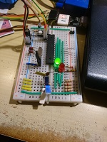
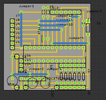
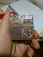
It then became clearer what the final dimensions should be. The next PCB design (for the Binary Numbers module) already was the final size, although the pin configuration for the ATMega changed again later. This can be compensated in software, so this module became the first fully functional prototype.
A thin plywood was on hand, those were the first cover plates.
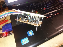
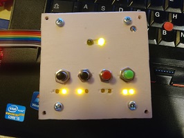
The next focus was the full system. The timer got most of its functions now. To test it, a system was built with two test modules and the timer on breadboards along with the completed Binary Numbers module.
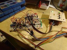
Once things were working well here, I designed PCBs for the timer and five more modules — plus a seventh module designed by Valsev and Seval during one of my programming workshops.
These PCBs became the first seriously playable prototype.
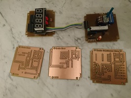
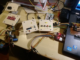
So by the end of 2018, in Version 1, I had the following modules along with the timer:
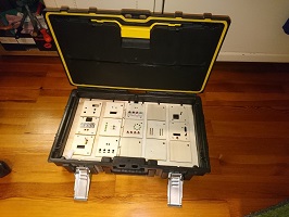
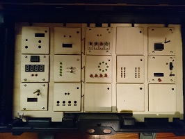
After finishing my last university exam in summer 2019, I finally had time to do a revision and design a few new modules. The first step was to switch from using Fritzing to using KiCad. Fritzing is good for beginners but quickly reaches its limits with larger PCB sizes or non-standard parts. KiCad is free and better suited for professional development. Of course it's more complex, but watching some tutorials before I started my actual design, made the transition relatively easy.
I then transferred all existing modules to the new software, implemented several essential improvements, such as a bus connector with reverse polarity protection.
New additions include the Volt Meter and Shift Register modules, along with two “needy” modules and two purely cosmetic modules (fan and batteries).
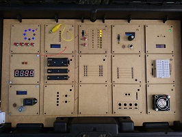

I continued to improve the manual as well. In this version, I introduced the option to switch the bomb to a simplified mode, making it accessible to people without prior experience.
I also wrote an article for "AATiS Praxisheft 30", describing the diy kit.
I even had the opportunity to write my Master’s thesis (starting December 2019) about this project. After finishing writing, while waiting for proofreading and printing, I couldn’t resist continuing development, resulting in five more modules:
Meanwhile, a workshop at the AATiS congress in Goslar was planned, but got canceled due to the COVID 19 pandemic. Since March 2020, the timer and the first four modules have been available as a kit from AATiS. In March 2021, the large case, an improved timer, and modules 05 to 09 and 50 followed, and again modules 10 to 13 and 52 followed in March 2023.